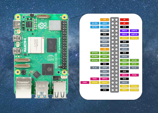
The Raspberry Pi 5 is a popular choice for low cost self built astronomy and astrophotography applications, including projects like INDI-AllSky benefiting from its GPIO (General-Purpose Input/Output) capabilities. Understanding its pinout is crucial for developers looking to leverage its capabilities. This guide breaks down each pin’s function and usage.
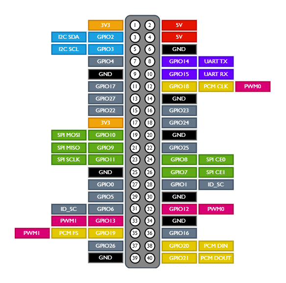
GPIO Schematic

The 40-pin header is arranged in two rows of 20 pins each. Below is a breakdown of these pins by function.
Power Pins on the Raspberry Pi 5
The power pins provide direct voltage outputs for powering external components:
- Pin 2, Pin 4: 5V Power Output – Supplies a constant 5V, suitable for powering sensors, motors, and other components.
- Pin 1, Pin 17: 3.3V Power Output – Provides a 3.3V output, useful for components operating at lower voltage.
- Ground (GND) Pins: Located at Pins 6, 9, 14, 20, 25, 30, 34, 39, used for establishing a common reference voltage.
General-Purpose Input/Output (GPIO) Pins
GPIO pins can be configured as input or output, enabling interaction with various components such as LEDs, buttons, and sensors.
| Pin Number | GPIO Number | Function |
|---|---|---|
| 3 | GPIO 2 | I2C SDA (Data Line) |
| 5 | GPIO 3 | I2C SCL (Clock Line) |
| 7 | GPIO 4 | General-purpose / PWM output |
| 8 | GPIO 14 | UART TX (Transmit) |
| 10 | GPIO 15 | UART RX (Receive) |
| 11 | GPIO 17 | General-purpose input/output |
| 12 | GPIO 18 | PWM (Pulse Width Modulation) |
| 13 | GPIO 27 | General-purpose input/output |
| 15 | GPIO 22 | General-purpose input/output |
| 16 | GPIO 23 | General-purpose input/output |
| 18 | GPIO 24 | General-purpose input/output |
| 19 | GPIO 10 | SPI MOSI (Master Out Slave In) |
| 21 | GPIO 9 | SPI MISO (Master In Slave Out) |
| 22 | GPIO 25 | General-purpose input/output |
| 23 | GPIO 11 | SPI SCLK (Clock) |
| 24 | GPIO 8 | SPI CE0 (Chip Enable 0) |
| 26 | GPIO 7 | SPI CE1 (Chip Enable 1) |
| 27 | GPIO 0 | Reserved for ID EEPROM |
| 28 | GPIO 1 | Reserved for ID EEPROM |
| 29 | GPIO 5 | General-purpose input/output |
| 31 | GPIO 6 | General-purpose input/output |
| 32 | GPIO 12 | PWM output |
| 33 | GPIO 13 | PWM output |
| 35 | GPIO 19 | SPI or PWM output |
| 36 | GPIO 16 | General-purpose input/output |
| 37 | GPIO 26 | General-purpose input/output |
| 38 | GPIO 20 | SPI output |
| 40 | GPIO 21 | SPI output |
Communication Protocols on GPIO Pins
I2C (Inter-Integrated Circuit)
I2C is a multi-drop bus, multiple devices can be connected to these same two pins. Used for sensors reading temperature, relative humidity, air pressure, and anything else you may want to sample. INDI-AllSky supports a good range of different compatible sensors.
- Pin 3 (GPIO 2) – SDA: Data line for I2C communication.
- Pin 5 (GPIO 3) – SCL: Clock line for I2C communication.
SPI (Serial Peripheral Interface)
SPI lets you attach multiple compatible devices to a single set of pins by assigning them different chip-select pins. Also used for sensors reading temperature, and relative humidity. Again, INDI-AllSky supports a good range of different compatible sensors.
- Pin 19 (GPIO 10) – MOSI: Sends data from the Raspberry Pi.
- Pin 21 (GPIO 9) – MISO: Receives data from SPI devices.
- Pin 23 (GPIO 11) – SCLK: Clock signal for SPI communication.
- Pin 24 (GPIO 8) – CE0: Chip Enable 0 for selecting SPI devices.
- Pin 26 (GPIO 7) – CE1: Chip Enable 1 for selecting SPI devices.
UART (Universal Asynchronous Receiver/Transmitter)
Users commonly control the Pi 5 over the GPIO using UART or access kernel boot messages from the serial console, which the system enables by default.
- Pin 8 (GPIO 14) – TXD: Transmit data.
- Pin 10 (GPIO 15) – RXD: Receive data.
PWM (Pulse Width Modulation)
PWM is a method of creating an analog voltage by toggling a digital pin on and off. Used for dimming LEDs, controlling motor or fan speed, or regulating a dew heater.
- Pins 12 (GPIO 18) and 32 (GPIO 12) – PWM0
- Pins 33 (GPIO 13) and 35 (GPIO 19) – PWM1
PCM (Pulse-coed Modulation)
PCM is a digital representation of sampled analog. On the Raspberry Pi, a DAC interprets this form of digital audio output to produce high-quality sound.
- Pin 38 (GPIO 20) – DIN
- Pin 40 (GPIO 21) – DOUT
- Pin 35 (GPIO 19) – FS
- Pin 12 (GPIO 18) – CLK
Astrophotography and Astronomy Applications for the Raspberry Pi 5
Astronomy enthusiasts widely use the Raspberry Pi 5 for projects, especially astrophotography and all-sky camera setups.. Some notable projects include:
- AllSky Cameras with INDI-AllSky
- INDI-AllSky allows users to set up an all-sky camera for night-sky imaging. You can use the GPIO pins to control focusers, sensors, dew heaters, and actuators for lens and dome covers.
- The Raspberry Pi 5’s improved processing power makes it well-suited for capturing and processing night sky images.
- Automated Telescope Control
- GPIO pins can interface with stepper motor drivers, enabling precise focusing and movement of telescopes for tracking celestial objects.
- The Raspberry Pi can run Ekos and INDI software, controlling mounts, cameras, and focusing mechanisms.
- Meteor Detection Systems
- DIY meteor detection setups use Raspberry Pi GPIOs to trigger recordings based on motion detection.
- Sensors such as light sensors or radio antennas can interface via GPIO to detect meteors.
- Star Tracking and Deep-Sky Imaging
- Many photographers use the Raspberry Pi to automate long-exposure deep-sky imaging.
- PWM pins can control cooling fans for temperature regulation in astrophotography setups.
- Automated Observatory Control
- Sensors connected directly or indirectly through API calls to weather sources can detect unsafe weather conditions, with relays and motors controlling the opening and closing of observatory covers.
Important Considerations
- The Raspberry Pi 5 operates at 3.3V logic levels; connecting components that use 5V logic directly to GPIOs may damage the board.
- The software configuration can multiplex some pins to serve multiple functions.
- Grounding is crucial for stable operation; ensure all external circuits share a common ground with the Pi.
Conclusion
The GPIO header on the Raspberry Pi 5 offers an array of functionalities, supporting multiple communication protocols and allowing for advanced project development. Whether you’re interfacing with sensors, controlling actuators, or communicating with other microcontrollers, understanding the pinout is essential for maximizing the potential of your Raspberry Pi 5.
